Controlling Relays With a Raspberry Pi.
Prelude
I was asked to code an API and build the basic circuitry of a Remote Controlled Locker Unit.
Once done, I decided to make a template API with a Front-End for any type of Raspberry Pi based Relay project.
Basically, we’ll have a Raspberry Pi controlling a set of relays.
They relays will turn or off whatever is connected to them.(There’s also a “On/Wait/Off” endpoint (and button) that’ll allow you to turn the relay ON then turn if off again after a configurable ammount of seconds. That can be useful to unlock magnetic locks or to flash a light etc.
The backend will consist of a Flask API, and a front end for manual testing and a few configurations is also provided.
Let’s do this!"
Requirements:
- Raspberry Pi with its recommended power supply (Power requirements differ per model).
- Relay module(s) (Max is 24 as the Raspberry Pi has a maximum of 24 GPIO pins).
- Jumper Wires (female to female).(The number of jumpers should be the number of desired locks + 2)
- Electrical Spool (I like to use Red and Black for obivous reasons).
- Optional: Luster clamp. (Single terminal)
- YOUR_DEVICE (Whatever it is you want to control using the relays. ie: light, magnetic-lock, etc.)
- Power Supply rated for YOUR_DEVICE.
Basic Usage:
Please note: The (<device_id>) count starts at 0.
(For example, devices 1 to 8 are actually indexed as 0 to 7.)
The endpoints are:
/api/devices/<device_id>/on/api/devices/<device_id>/off/api/devices/<device_id>/flash/api/device/<int:lock_id>/status/api/devices/api/config/set_max_devices/api/config/set_max_devices
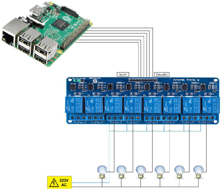
Wiring
- Raspberry Pi 5V pin connect to the relay module’s VCC pin.
- Raspberry Pi GND pin connect to the relay module’s GND pin.
- Raspberry Pi GPIO pins connect to the relay module’s IN pins.(Sometimes called Signal pins)
- If you have more than one realy, create jumpers between all the relay common inputs if you want them to use the same power source.
- The ‘Hot’ from YOUR_DEVICE(s) connects to one of the relays’ N.O input. (N.O:Normally Open)
If you have multiple devices, each device should be connected to its own relay. - The ‘GND’ from your device(s) connect to a single Luster clamp that connects to the power supply’s GND.
Raspberry Pi Pin-Layout
Here you see the pin number, its general funcionality and it’s specific device number as pertaining to my API.
Essentially, the device number here will correspond to the device number you’ll enter in the API call to control said device.
(Just incase my illustration isn’t clear, the stars represent the pinout.:) )
+-----+--------------|----------+       +----------+-----------+-----|
| Pin |  Function    | Device # |       | Device # |  Function | Pin |
+-----+--------------|----------+       +----------+-----------+-----|
| 1   | 3.3V PWR     |          | *   * |          | 5V PWR    | 2   |
| 3   | GPIO 2 / SDA | Device 1 | *   * |          | 5V PWR    | 4   |
| 5   | GPIO 3 / SCL | Device 2 | *   * |          | GND       | 6   |
| 7   | GPIO 4       | Device 3 | *   * |          | UART0 TX  | 8   |
| 9   | GND          |          | *   * |          | UART0 RX  | 10  |
| 11  | GPIO 17      | Device 4 | *   * | Device 15| GPIO 18   | 12  |
| 13  | GPIO 27      | Device 5 | *   * |          | GND       | 14  |
| 15  | GPIO 22      | Device 6 | *   * | Device 16| GPIO 23   | 16  |
| 17  | 3.3V PWR     |          | *   * | Device 17| GPIO 24   | 18  |
| 19  | GPIO 10      | Device 7 | *   * |          | GND       | 20  |
| 21  | GPIO 9       | Device 8 | *   * | Device 18| GPIO 25   | 22  |
| 23  | GPIO 11      | Device 9 | *   * | Device 19| GPIO 8    | 24  |
| 25  | GND          |          | *   * | Device 20| GPIO 7    | 26  |
| 27  | Reserved     |          | *   * |          | Reserved  | 28  |
| 29  | GPIO 5       | Device 10| *   * |          | GND       | 30  |
| 31  | GPIO 6       | Device 11| *   * | Device 21| GPIO 12   | 32  |
| 33  | GPIO 13      | Device 12| *   * |          | GND       | 34  |
| 35  | GPIO 19      | Device 13| *   * | Device 22| GPIO 16   | 36  |
| 37  | GPIO 26      | Device 14| *   * | Device 23| GPIO 20   | 38  |
| 39  | GND          |          | *   * | Device 24| GPIO 21   | 40  |
+-----+--------------|----------+       +----------+-----------+-----|
Code
As this is an ongoing project, I will soon have an open source version available for public use.